Over the past few years, the United States has imported (and exported) about 8.5 million barrels per day of petroleum[1]. Assuming that one barrel is worth $75, (the price of a barrel of crude oil on March 1, 2023), then the amount of petroleum traded by the U.S. comprises a total of roughly 230 billion dollars per year. Assuming these figures, a 1 % error in the measurement of petroleum products equals 2.3 billion dollars on a yearly basis. It is fairly obvious that the accuracy of these measurements is therefore crucial.
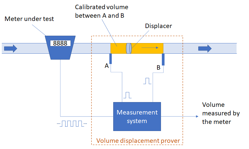
To measure the continuous flow of liquid that travels through a production pipeline, a meter is installed in that pipeline. But how do you regularly check the accuracy of the meter without removing the meter, discontinuing the flow of product, or discontinuing the metering process? The answer is a volume displacement prover.
Many petrochemical installations contain a permanent pipe prover. A pipe prover is a volume displacement prover, using a sphere as displacer instead of a piston. In general, pipe provers need a relatively large pipe segment to produce accurate measurement results, and are therefore large installations, not suitable for mobile use. But due to developing technology, small volume provers now form a viable alternative. They are smaller than pipe provers and can therefore be used in a mobile configuration. This makes the Small Volume Prover (SVP) suitable for use by local weights and measures offices.
In February 2023, NIST OWM staff were invited to observe a calibration of a small volume prover by the Michigan Department of Agriculture's E.C. Heffron state metrology laboratory. The goal was to learn more about the calibration procedures deployed in the state metrology laboratories, and to determine the critical factors that play a role in those procedures. The Michigan state metrology lab calibrates approximately 15 SVPs per year ranging in capacity from 5 gallon to 30 gallon. These provers are mainly used by petrochemical industry.
Measurement principle of SVPs
An SVP is referred to as a "volume displacement prover." The principle of a volume displacement prover is rather simple. A volume displacement prover consists of a pipe with a known capacity, a device for displacing fluid through the pipe, and sensors that detect when the fluid has reached the beginning and end of its travel through the pipe.
The SVP includes a bar fitted with two sensors as shown in Figure 1 as "A" and "B." The exact volume between the two sensors is verified during the calibration of the SVP in a laboratory. The meter under test generates a pulse for every unit of volume that passes through the meter. The prover is installed in line with the meter, so they are both measuring the same amount of liquid. Inside the prover, a displacer travels with the liquid through the pipe. When the displacer passes a certain start point in the pipe, point A, a trigger is given to start a measurement. From that moment on the measurement system connected to the prover starts counting the pulses generated by the meter. When the displacer passes a second point in the pipe, point B, another trigger is generated to stop the count of pulses. The liquid moving through the meter is not the same exact liquid as is simultaneously being measured by the SVP. However, the quantities of liquid are the same. That is, the amount of liquid that traveled from point A to point B is the same as the amount of liquid traveled through the meter during the time that it took for the displacer to travel from point A to point B. Since the exact volume of the section between point A and point B is known, this predetermined volume should match with the number of pulses received from the meter multiplied by the volume per meter pulse.
An SVP uses a piston as displacer. The piston is connected to a shaft that terminates outside the enclosure. On the piston shaft there is a trigger mounted that activates the sensors on the adjacent sensor bar, as the piston moves along the shaft. The distance (d) between the sensors defines the calibrated volume within the enclosure (Figure 2).
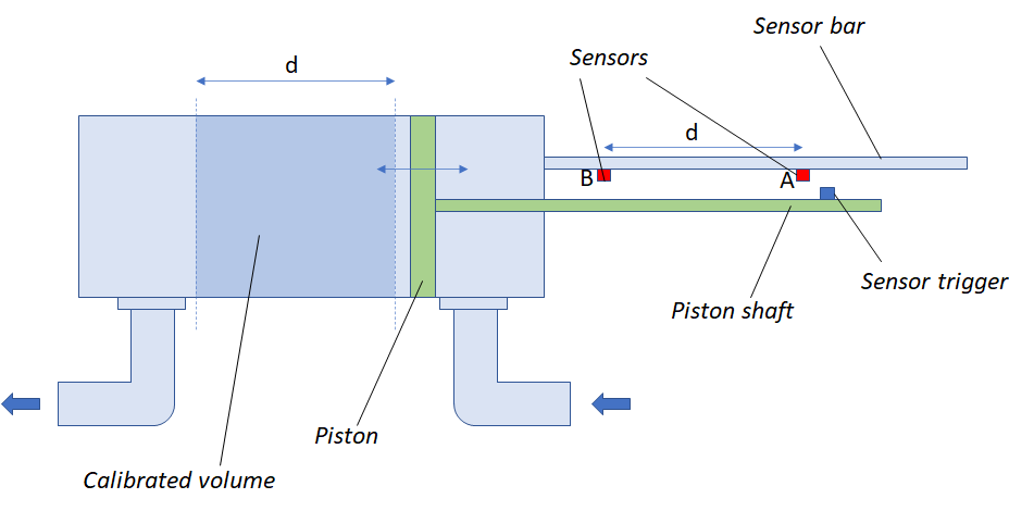
The piston has a seal to make sure no liquid passes the piston unintentionally (while the piston moves across the calibrated volume). The piston has a poppet valve that opens when the piston is being retracted to the staring position. That way, the flow of liquid is not interrupted.
Calibration of the SVP
The Michigan state metrology laboratory applies NIST Standard Operating Procedure 26 for the calibration of their SVPs. The objective is to calibrate the internal volume of the small volume prover between the two trigger points (the calibrated volume). At the end of the calibration process, the calibrated volume is then compared to the volume determined during the last calibration to detect any drift that could indicate a defect in the prover. The applied tolerance for the repeatability is 0.02 %.
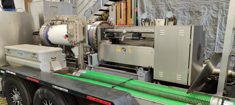
It is important that the flow and consistency of the fluid used during the calibration process is consistent throughout the measurement. For the calibration procedure, the Michigan state lab uses demineralized water that is stored in a 2,000-gallon (7500-liter) tank to provide a sufficiently constant pressure. Before the actual calibration, the prover is filled with water and all air is vented. See a mobile SVP mounted on a vehicle trailer in Figure 3.
Courtesy of the Michigan state metrology laboratory
When starting the measurement, water is flowing through the system, slowly pushing the piston forward. At first, the sensor trigger on the piston shaft has not yet reached the starting sensor, and water coming out of the system is drained. When the trigger reaches the first sensor (i.e., the piston has reached the start of the calibrated volume), water exiting the system is automatically diverted to a tank where it is collected. When the trigger reaches the second sensor (i.e., the piston has reached the end of the calibrated volume), the exiting water is automatically diverted back to the drain. With a constant flow, the amount of water collected in the tank is exactly the same as the amount of water that is being held in the calibrated volume inside the prover.
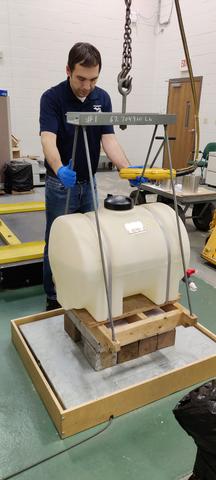
The lab uses a gravimetric method to determine the amount of water in the tank. The tank is weighed on a scale before and after being filled with water. A 600 kg x 0.1 g scale is utilized as a mass comparator for the calibration procedure to guarantee the highest possible accuracy (Figure 4).
Courtesy of the Michigan metrology laboratory
The difference between the two weighments is the weight of the water in the tank. The weight of the water is converted into a volume according to the calculations provided in NIST SOP 26. Corrections are applied for the temperature and pressure of the water inside the prover. For this purpose, the lab has attached a calibrated pressure sensor on an access point on the prover and placed a calibrated temperature sensor in a thermowell in the enclosure of the prover.
Ideally, the calibration procedure is performed at a flow rate similar to that of the prover when it is being used at in the field. But this is not always possible for many State laboratory operations. A 20-gallon prover (similar to the prover that was being calibrated during our visit) has a normal operating flow rate of approximately 500 gallons per minute. With the test setup in the Michigan state lab, the maximum achievable flow rate is approximately 3 gallons per minute.
To check the performance of the piston seals, the calibration procedure is performed at a high flow rate (approximately 3 gal/min) and then at a low flow rate (approximately 2 gal/min). The test is performed five times in the following flow rate sequence: high - low - high - low - high. The difference between the results at the high and low flow rate is then closely examined since a any variation is often an indication of fluid seeping through the seals of the piston. If there is a significant change in the calibrated volume after calibration, then the new calibrated volume is entered in the prover's measuring system control software.
SVP Influence Factors
Small volume provers can accurately detect a predetermined amount of fluid displacement. As described in this article, several critical influence factors need to be considered during operation to ensure reliable performance.
Controlled Flow. It is vital that no liquid seeps past the piston when it is moving along the calibrated volume in the prover. A seal around the piston prevents liquid seeping between the piston and the enclosure. Another seal on the poppet valve prevents liquid seeping through the valve during the measurement. Both seals are subject to wear and tear. It is vital that the seals are periodically replaced to ensure accurate measurement. Some provers have a leak detection feature which detects any leaks in the piston seals. Other provers provide an automatic recording of the number of operations as an indicator of the age of the seals, which allows the operators to plan for an appropriate lifecycle replacement schedule.
Flow Consistency. Another factor that plays a role in the accuracy of the measurement is the consistency of the flow and the composition of the fluid (i.e., the fluid is free of air bubbles and contamination from inhomogeneity). Since the small volume prover and the meter are installed at different positions in the pipeline, the prover is not measuring the identical batch of fluid as the meter is measuring during the measurement. Therefore, small volume provers can only be used in situations where there is a relatively constant composition of the product.
Temperature. A third factor that has a major impact on the measurement is temperature. When temperature rises, the enclosure of the prover expands, and so does the calibrated volume. In reality, the temperature of the enclosure is mainly determined by the temperature of the liquid flowing through the prover. Another place where temperature plays a role is the sensor bar. This part is located outside the compartment where fluid is flowing and therefore more susceptible to environmental influences. The temperature of the sensor bar is important because if the temperature rises, the sensor bar expands and with that the distance between the two sensors, and thus also the calibrated volume. The prover's software compensates for both the fluid temperature and the temperature of the sensor bar during the calibration of a meter.
Acknowledgment
We would like to thank the state of Michigan, and particularly the lab specialists of Michigan state's E.C. Heffron metrology laboratory, for the invitation, their hospitality, and their input for this newsletter. Click here to learn more about the Michigan Laboratory Division, which includes both the metrology laboratory and food safety and livestock testing laboratory, as well as their weights and measures, motor fuels quality, and environmental protection programs.


